
Introduction
A particulate system has a set of two filters – one for sample and one for purge. The sample filter protects the sample pump from the particle-laden sample air. The purge filter cleans purge air during the automatic zero.
If the sample and purge filters aren’t changed at appropriate intervals, the filters can become overly laden (saturated) with particle matter. When the monitor runs its regular auto zero check, purge air passes through the purge filter and through the optics of the engine. If there’s excessive particle matter in the purge filter, this can contaminate the purge airstream. This causes the H0 value, which controls the zero of the module, to be set too high and causes negative particle matter readings.
To understand how often you should perform this service activity, click here.
-
-
Enter service mode so any fluctuations in the data caused from this activity can be excluded from air quality reports.
-
-
-
The filters for the particle monitor are located inside the optical engine.
-
-
-
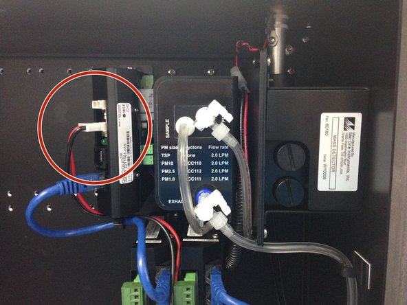
Stop the the sample and purge pumps by pulling out the black and red power cables from the electronics module.
-
-
-
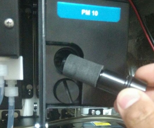
Unscrew the top sample inlet filter from the side of the optical engine.
-
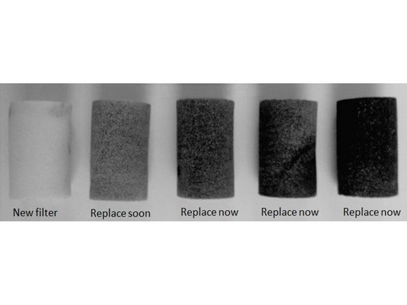
If the filter needs replacing, slide the dirty filter off the filter mount and put on a new one.
-
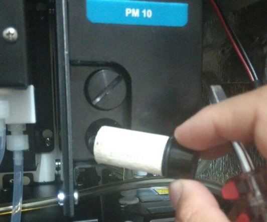
Screw in the new sample inlet filter.
-
Repeat for the bottom purge filter.
-
Reconnect the sample and purge pumps to the electronics module.
-
-
-
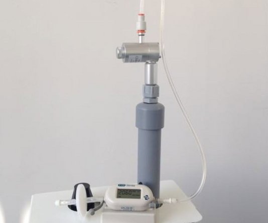
Measure the inlet's flow rate to ensure you've fitted the filters correctly.
-
The flow rate should be 2.0 LPM. If the flow is lower, check the filters are screwed all the way into the optical engine.
-
-
-
For extra help, watch our video.
-


For further support, contact Technical Support.
For further support, contact Technical Support.
Cancel: I did not complete this guide.
2 other people completed this guide.
