Introduction
Span calibration should only be performed on modules that’ve been successfully zero calibrated. Span calibration can be performed either via dilution calibration using higher concentration gases or direct calibration using bottled gas at your desired calibration concentration. This set of instructions covers direct calibration.
It is performed module by module, one at a time. Each gas module takes between 20 and 40 minutes to calibrate with span gas. Gains are applied using either the Manual Entry or the Calibration areas of the Calibration and Service page.
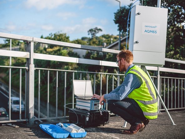
This procedure can be used for either AQS1 or AQM65 instruments.
The sensors in Aeroqual's gas modules require oxygen to operate correctly. Gas modules can be span calibrated from gas cylinders in a balance of air to achieve this.
We recommend you leave any failed modules running in the monitor throughout the zero and span calibration process. After you’ve calibrated the remaining modules, you can open the door to the monitor and remove the failed modules for inspection.
There is no specific recommended span concentration for each gas module.
The calibration engineer should choose a span gas concentration which best suits their calibration needs: Two possible approaches to choosing a span gas concentration are:
- A span gas concentration can be chosen which best represents the concentrations expected at the measuring site.
- A span gas concentration can be chosen which is at 80 % of the full measurement range of the module. This is an approach specified by some manufactures and is written in to the standard operating procedures of some municipal monitoring networks based on reference monitoring equipment.
For example: At your measurement location the range of CO concentrations measured are between 1 and 8 ppm with an average of 4 ppm. You might choose to calibrate the CO module at 5 ppm which in the middle of the expected measurement range and just above the average expected concentration. Or you might just calibrate the CO module at 20 ppm which is 80 % of the full range (0 to 25 ppm).
Tools
Parts
-
-
This guide assumes:
-
You've already done a zero calibration.
-
You've got the correct gas cylinders with gas concentrations that suit your calibration needs.
-
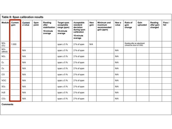
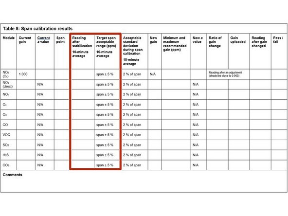
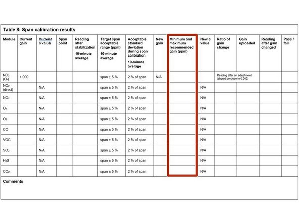
Start by recording the current gains for each gas module in the Current gain column in table 8 of the calibration table.
-
-
-
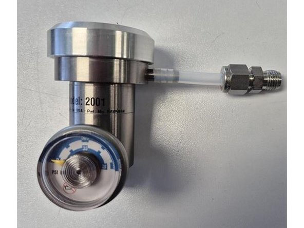
If not already fitted, connect 5cm of tubing with Swaglok union to your flow regulator.
-
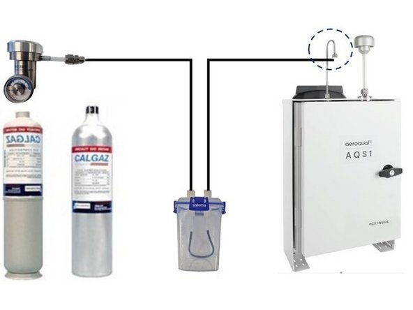
Connect your flow regulator to your gas cylinder.
-
Remove the Kynar fitting (inlet mesh filter) from the monitor’s gas inlet.
-
Connect the 3-way tee to the inlet.
-
Add 17oz(500ml) of water to the humidifier.
-
Connect the two lengths of ¼” Teflon tubing to the humidifier. One tube goes to the flow regulator, the other to the tee.
-
If you’re using a demand flow regulator, close (cap) the other side of the tee.
-
If you’re using a fixed or adjustable flow regulator, add a length of tubing to the other side of the tee to exhaust the excess gas away from you.
-
-
-
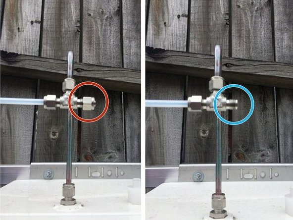
Open the regulator and start supplying gas at your chosen span point. For fixed and variable regulators make sure excess flow is coming out of the exhaust tubing.
-
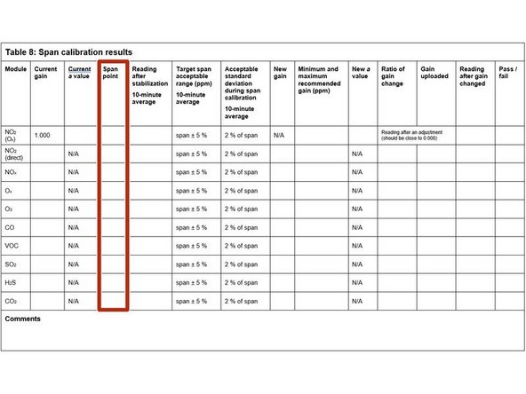
Record your span gas concentrations in the Span point column.
-
-
-
Wait 30 to 40 minutes for the module readings to stabilize towards span air.
-
To determine if stabilization is successful:
-
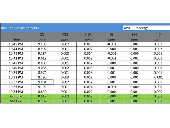
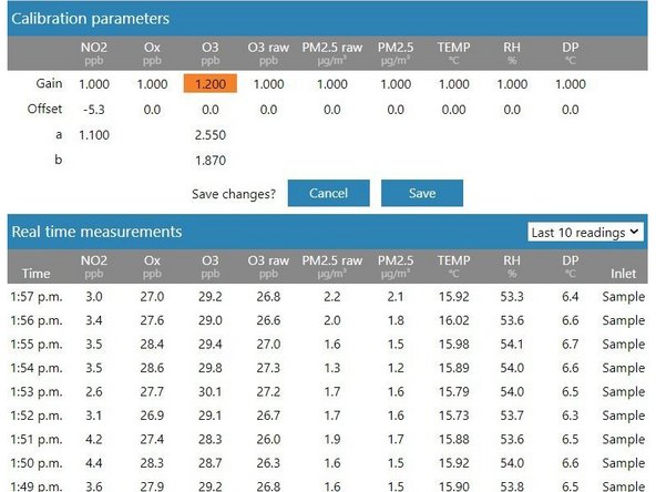
Look at the standard deviation over a ten-minute period in the Manual Entry (shown) or Calibration areas of the Calibration and Service app.
-
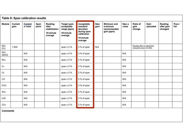
See if they fall within the acceptable range listed in the Acceptable standard deviation during span calibration column of your calibration table.
-
-
-
Record the stabilized reading from the 10-minute average in the Reading after stabilization column.
-
If the stabilized value is within the accepted range (see Target span acceptable range column), no gain adjustment is needed. Write pass in the Pass / fail column and move on to next module.
-
If the stabilized value is outside the accepted range, you need to make a gain adjustment.
-
-
-
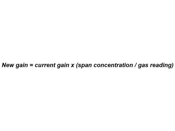
If you're using the Manual Entry area to upload gain adjustments, you need to calculate your new gain using the equation shown.
-
To make the calculation, you need to know the:
-
Current gain
-
Span gas concentration
-
Gas module reading
-
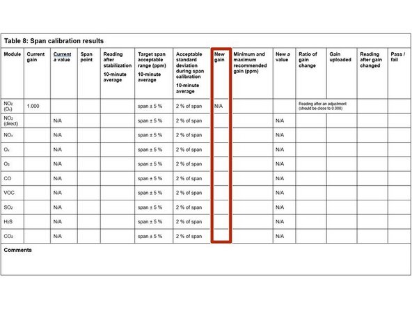
Record the calculated gain in the New gain column.
-
-
-
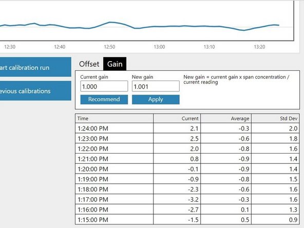
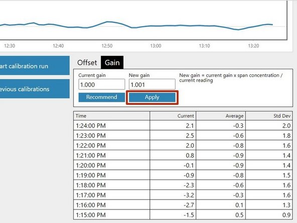
If you're using the Calibration area to upload gain adjustments, select the correct gas channel and click the Recommend button to calculate the gain for your selected gas.
-
Record the calculated gain in the New gain column.
-
-
-
If the new offset is within the accepted range (see the Minimum and maximum recommended gain column), you can upload your new gain.
-
If you're using the Manual Entry area, click the appropriate cell, type in the new value and click Save.
-
If you're using the Calibration area, simply click the Apply button.
-
It might take several minutes for the gain to be applied and to see the changed readings.
-
If the new gain is outside the accepted range, don’t upload the gain. Write fail in the Pass / fail column and move on to next module.
-
-
-
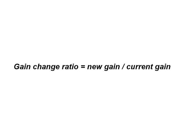
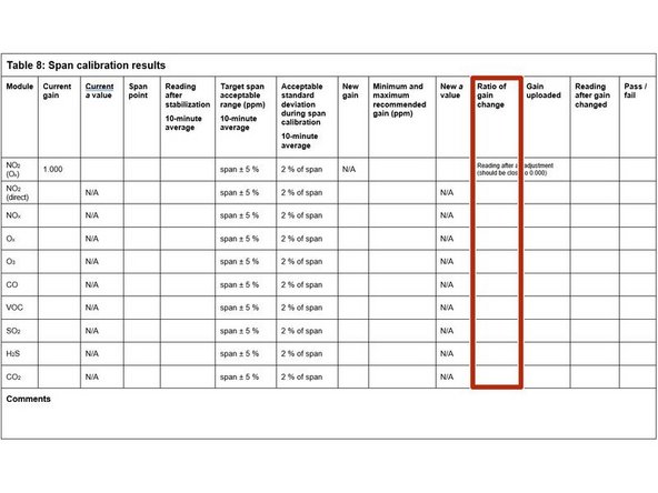
Calculate and record the ratio of the gain change using the equation shown.
-
Record the ratio in the Ratio of gain change column.
-
-
-
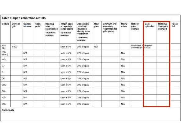
Record the offset you uploaded in the Gain uploaded column.
-
Wait 2 or 3 minutes then record the current reading in the Reading after gain changed column.
-
Confirm the reading is within acceptable limits. If yes, write pass in the Pass / fail column. If not, write fail.
-
-
-
Close your regulator and disconnect the gas cylinder. Connect a cylinder of zero air and flow air for 10 minutes to purge (clean) the gas lines.
-
Move on to span calibrating the next module if required.
-


For further support, contact Aeroqual Support.
For further support, contact Aeroqual Support.