
Parts
No parts specified.
-
-
Remove the front panel cover to reveal the monitor's AC junction box (left) and compressor cassette (right).
-
Remove the AC junction box cover.
-
-
-
Feed the mains power cable through the gland on the bottom of the junction box.
-
Wire in the cable (earth, ground, power).
-
The output from the junction box goes straight inside the enclosure and connects to the 12 V rail. The live lead is connected through the 5A fuse.
-
-
-
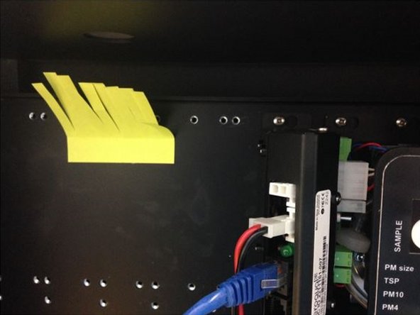
Make sure the 12V DC fuse in the 12 V rail is out (this means the monitor is turned off).
-
Switch on mains AC power.
-
The internal fan will start up and begin circulating air inside the box. Air will come out the top vent. Nothing else should be on.
-
-
-
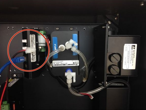
To test 12V DC power to the rest of the monitor:
-
Disconnect the red/back power cable from the pump module. (This prevents any damage to the optical engine.)
-
Turn on the monitor by pushing the 12V DC fuse into the fuse holder.
-
The pump/s will start and the ePC will boot up with a series of beeps. The status LED lights on the modules, embedded PC and modem (if fitted) will turn green.
-
-
-
For extra help, watch our video.
-


For further support, contact Technical Support.
For further support, contact Technical Support.
Cancel: I did not complete this guide.
3 other people completed this guide.
