
Introduction
Use the procedure to ensure your monitor is fit for calibration. It involves checking key operating parameters such as flow rates and changing the gas inlet filter.
-
-
Download the calibration results form at the end of this user guide.
-
Fill in tables 1, 2 and 3.
-
These tables record basic details like date and time, site name, engineer's name, and the equipment that will be used during the calibration.
-
-
-
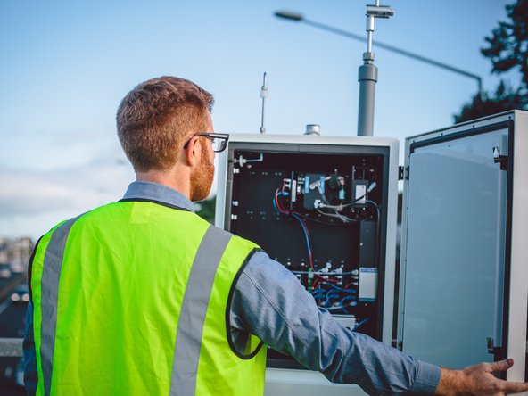
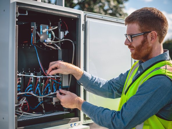
When arriving onsite, it's important to make sure no new emission sources or obstructions have appeared since the last visit.
-
Inspect the local surroundings and check for local point source emissions such as open fires or exhaust emissions from a newly positioned generator.
-
Check for obstructions which may affect the measurements, such as a new fence.
-
Record your observations in table 4 of the calibration form.
-
-
-
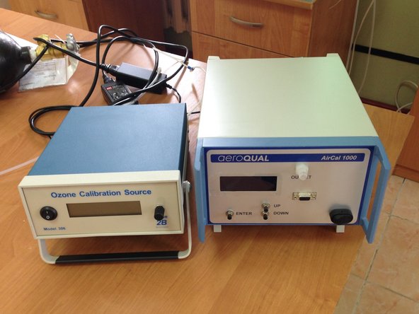
Because the AirCal 1000 and Ozone Calibration Source take at least 30 minutes to warm up and become stable, now is a good time to turn both on.
-
Turn on the AirCal 1000 calibrator and switch on the pump override switch on the back panel.
-
If you're calibrating ozone, turn on your Ozone Calibration Source and set it to deliver 0.1 ppm ozone. This allows time for the lamp to stabilize at 0.1 ppm.
-
-
-
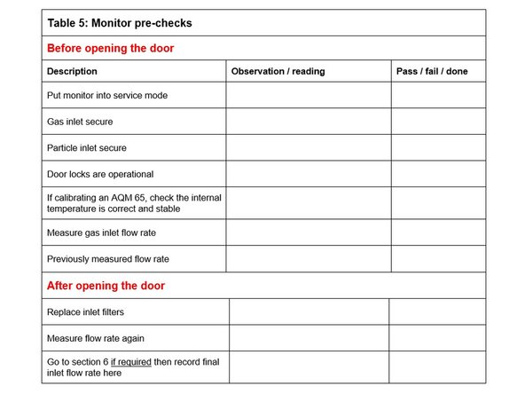
Fill in table 5 by completing the steps 2,3 and 4 in this user guide.
-
-
Check the gas inlet is secure.
-
Check the particle inlet is secure.
-
Check the door locks are operational.
-
-
-
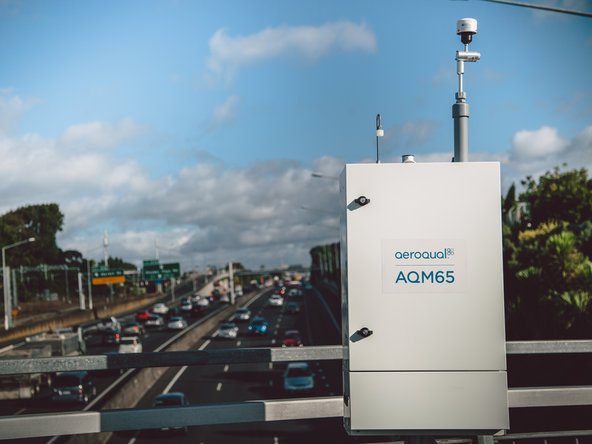
This step only applies to AQM 65 monitors.
-
If calibrating an AQM 65, check the internal temperature has been stable at the correct temperature.
-
If the internal temperature isn’t correct, you must address this before attempting a calibration.
-
-
-
-
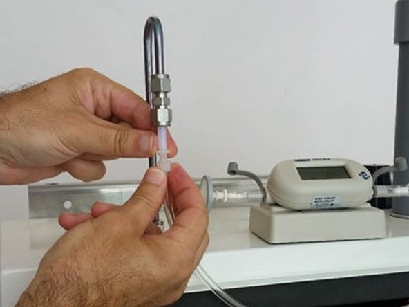
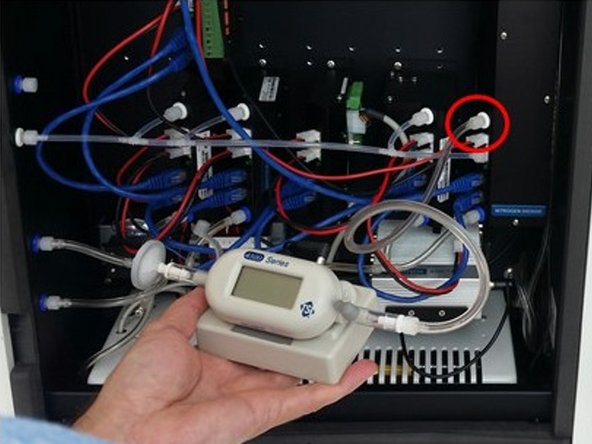
Record the previously measured flow rate. (You should find this in the monitor's journal.)
-
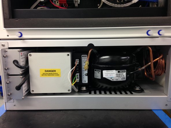
Open the monitor door and replace the gas inlet filer. Try to minimize the time the door is open so the sensors can quickly re-stabilize.
-
Measure and record the flow rate again.
-
If the inlet rate has changed from the previously recorded rate by less than ± 20 %, check the gas connections for obvious leaks, then use the flow adjustment valve to correct the flow. If the adjustment is unsuccessful, go to table 6 in the calibration form.
-
If the inlet flow has changed from the previously recorded rate by more than ± 20 %, go to table 6.
-
-
-
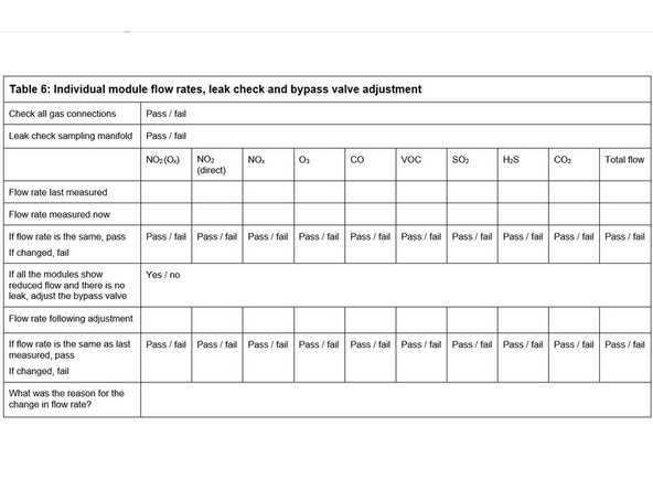
You only need to complete table 6 if the inlet flow rate was more than ± 20 % of the previously measured rate, or if using the flow adjustment valve to correct the inlet flow didn't work.
-
One or more modules can fail the flow check, but others can pass. Calibration can continue on modules that pass.
-
Modules that fail can be removed and checked without affecting the calibration on the remaining modules.
-
-
-
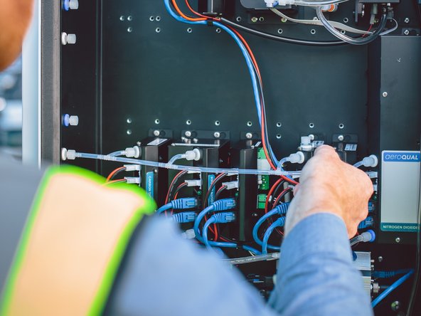
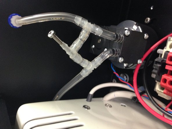
Check the individual gas connections for obvious leaks. If a leak is found, correct it.
-
Perform a leak check on the sampling manifold. If a leak is found, correct it.
-
-
-
It's important to have a high-quality flowmeter such as the TSI 4040 or the Bios Defender DryCal.
-
Record the individual flow rates the last time they were measured.
-
Measure and record today’s individual flow rates. Record the total flow.
-
For each module, if the flow rate now equals the previously measured flow rate (± 20 % LPM), pass that module. Otherwise fail it.
-
If no specific module is causing a problem and all module flow rates are low, adjust the flow rate using the bypass valve.
-
-
-
If no specific module is causing a problem and all module flow rates are low, adjust the flow rate using the bypass valve.
-
Re-measure and record flow rates for each module.
-
If the flow rate now equals the previously measured flow rate, pass it.
-
-
-
For those modules which don’t have the correct flow rate and can’t be corrected with the bypass valve, perform a leak check or check for blockages.
-
If the problem can’t be corrected, remove the module and cap off the gas connections. Record fail in the form.
-
The total flow rate is reduced when a module is removed.
-
If the door is left open for the purpose of finding a leak or removing a module, the gas modules will become unstable and you'll need to wait 1 – 2 hours to allow the sensors to re-stabilize.
-


For further support, contact Technical Support.
For further support, contact Technical Support.
Cancel: I did not complete this guide.
2 other people completed this guide.
Attached Documents
