
Introduction
Span calibration should only be performed on modules that’ve been successfully zero calibrated.
It is performed module by module, one at a time. Each gas module takes between 20 and 40 minutes to calibrate with span gas. Gains are applied using either the Manual Entry or the Calibration areas of the Calibration and Service app.
If you have an AQS 1, use this procedure to span calibrate your NO2, CO and VOC gas modules. If you have an AQM 65, use it to span calibrate your NO2, NOx, SO2, CO, H2S and VOC gas modules.
If your monitor uses the Ox/O3 system to measure NO2, you can also use this guide to span calibrate your Ox module. Note: For monitors using the Ox/O3 system, you must calibrate the Ox and O3 before any other modules.
The sensors in Aeroqual's gas modules require oxygen to operate correctly. Gas modules can be span calibrated from gas cylinders in a balance of air to achieve this. Gas cylinders in a balance of N2 can only be used when diluted with air. A dilution ratio of 50x is sufficient for most applications. The Aeroqual AirCal1000's inbuilt zero-air generator can achieve this as it uses scrubbed ambient air as it's zero-air source.
We recommend you leave any failed modules running in the monitor throughout the zero and span calibration process. After you’ve calibrated the remaining modules, you can open the door to the monitor and remove the failed modules for inspection.
This procedure assumes you are familiar with how to operate the AirCal 1000.
To understand how often you should perform this service activity, click here.
There is no specific recommended span concentration for each gas module.
The calibration engineer should choose a span gas concentration which best suits their calibration needs: Two possible approaches to choosing a span gas concentration are:
- A span gas concentration can be chosen which best represents the concentrations expected at the measuring site.
- A span gas concentration can be chosen which is at 80 % of the full measurement range of the module. This is an approach specified by some manufactures and is written in to the standard operating procedures of some municipal monitoring networks based on reference monitoring equipment.
For example: At your measurement location the range of CO concentrations measured are between 1 and 8 ppm with an average of 4 ppm. You might choose to calibrate the CO module at 5 ppm which in the middle of the expected measurement range and just above the average expected concentration. Or you might just calibrate the CO module at 20 ppm which is 80 % of the full range (0 to 25 ppm).
-
-
This guide assumes:
-
You've already done a zero calibration and the AirCal 1000 is warmed up and stable.
-
The AirCal 1000 is already connected to the gas inlet via a 3-way tee that is open (uncapped) on one side.
-
You've got the correct gas cylinders with gas concentrations that suit your calibration needs. For gas cylinder guidelines, see here.
-
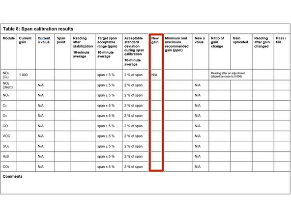
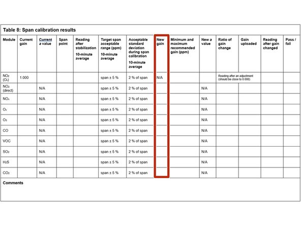
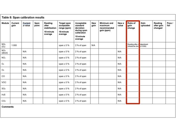
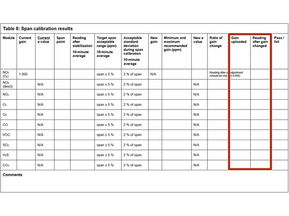
Start by recording the current gains for each gas module in the Current gain column in table 8 of the calibration form.
-
If an Ox module is fitted, NO2 doesn't have a gain adjustment.
-
-
-
Attach (screw on) a gas regulator on to each of your 2 gas cylinders.
-
Connect the gas regulators to the gas inlet ports on the back of the AirCal 1000. Use 1/8 inch OD Teflon tubing to make this connection.
-
Make sure the connections are leak tight.
-
-
-
Start the calibration gas flowing at your chosen span point.
-
Make sure there is excess flow out from the tee at the monitor inlet.
-
Record your span gas concentrations in the Span point column.
-
You should have also defined this in your calibration run.
-
-
-
Wait 30 to 40 minutes for the module readings to stabilize towards span air.
-
To determine if stabilization is successful:
-
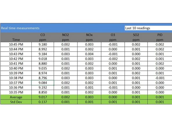
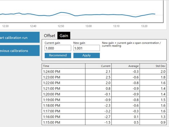
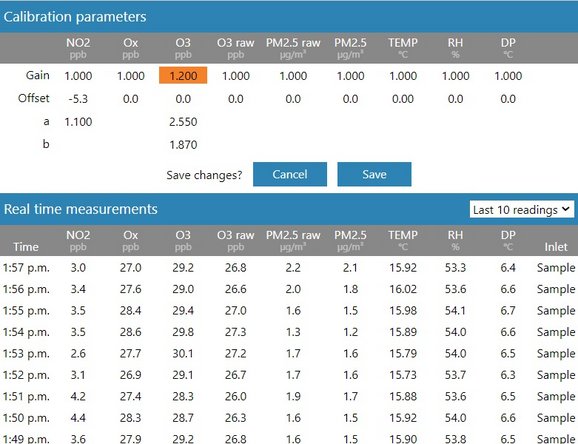
Look at the standard deviation over a ten-minute period in the Manual Entry (shown) or Calibration areas of the Calibration and Service app.
-
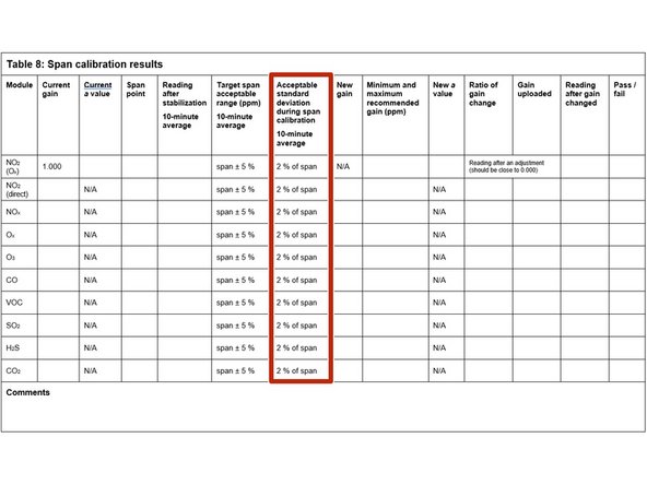
See if they fall within the acceptable range listed in the Acceptable standard deviation during span calibration column of your calibration form.
-
-
-
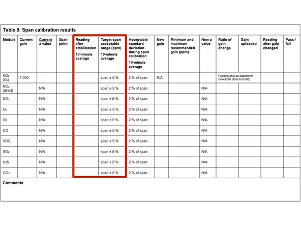
Record the stabilized reading from the 10-minute average in the Reading after stabilization column.
-
If the stabilized value is within the accepted range (see Target span acceptable range column), no gain adjustment is needed. Write pass in the Pass / fail column and move on to next module.
-
If the stabilized value is outside the accepted range, you need to make a gain adjustment.
-
-
-
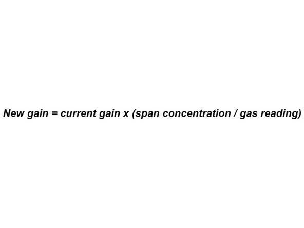
If you're using the Manual Entry area to upload gain adjustments, you need to calculate your new gain using the equation shown.
-
To make the calculation, you need to know the:
-
Current gain
-
Span gas concentration
-
Gas module reading
-
Record the calculated gain in the New gain column.
-
-
-
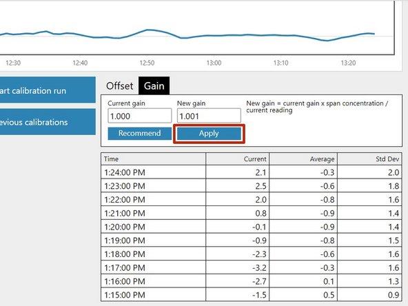
If you're using the Calibration area to upload gain adjustments, select the correct gas channel and click the Recommend button to calculate the gain for your selected gas.
-
Record the calculated gain in the New gain column.
-
To learn more about the functionality in the Calibration area, go here.
-
-
-
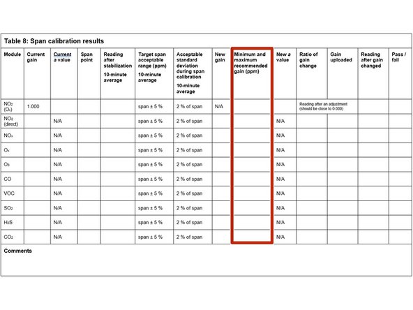
If the new gain is within the accepted range (see the Minimum and maximum recommended gain column), you can upload your new gain.
-
If you're using the Manual Entry area, click the appropriate cell, type in the new value and click Save.
-
If you're using the Calibration area, simply click the Apply button.
-
It might take several minutes for the gain to be applied and to see the changed readings.
-
If the new gain is outside the accepted range, don’t upload the gain. Write fail in the Pass / fail column and move on to next module.
-
-
-
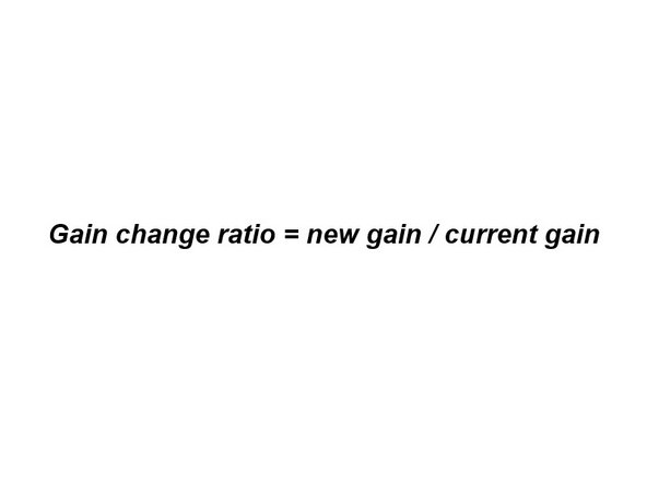
Calculate and record the ratio of the gain change using the equation shown.
-
Record the ratio in the Ratio of gain change column.
-
-
-
Record the offset you uploaded in the Gain uploaded column.
-
Wait 2 or 3 minutes then record the current reading in the Reading after gain changed column.
-
Confirm the reading is within acceptable limits. If yes, write pass in the Pass / fail column. If not, write fail.
-
Move on to next module.
-
-
-
Deliver zero air for 10 minutes to purge (clean) the gas lines.
-
Move on to next module.
-


For further support, contact Technical Support.
For further support, contact Technical Support.
Cancel: I did not complete this guide.
3 other people completed this guide.
