
Parts
-
-
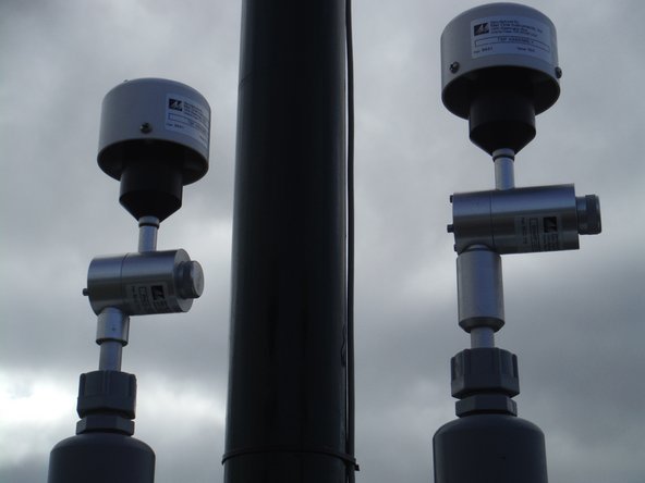
Assemble the particle monitor inlet by pushing together the following supplied components: inlet tube, cyclone adaptor, cyclone and TSP head.
-
The inlet tube is wrapped in a thin film 12V heater with protective grey sleeve. The heater reduces humidity in the sample air, preventing particle growth and fogging of the optics. The cable and plug power the heater.
-
-
-
Turn off the monitor by pulling the 12V DC fuse out from the fuse holder.
-
If you bought your monitor after October 2019, you can optionally turn the monitor off via the rotary switch in the bottom right hand corner of the enclosure.
-
-
-
Remove the protection tape from the inlet on the particle monitor or particle profiler.
-
Your monitor may come with a protection cap instead of tape.
-
-
-
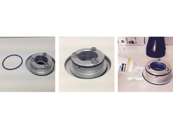
Attach an O-ring to the aluminum mounting ring on the roof of the monitor and apply a small amount of silicon lubricant.
-
-
-
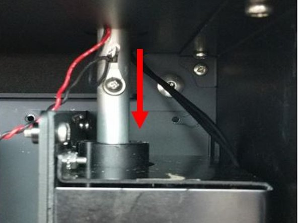
Carefully thread the aluminum inlet tube, as well as power cable and plug for the heater, through the mounting ring.
-
Push the tube all the way into the optical engine.
-
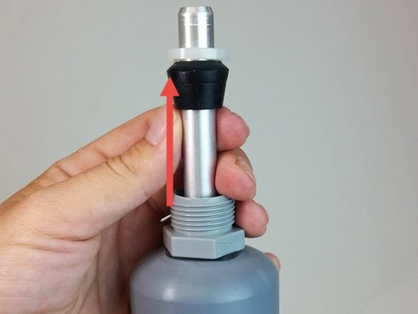
If it doesn’t go all the way in, add more length by:
-
Removing the grey retaining nut on the top of the inlet
-
Sliding the rubber grommet up the tube.
-
Replacing the nut.
-
-
-
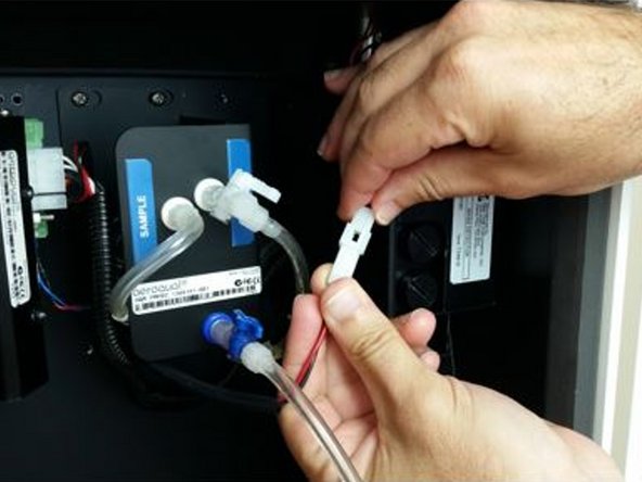
Connect the inlet’s heater plug to the plug coming from the optical engine.
-
-
-
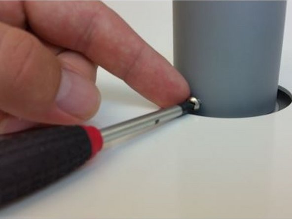
Align the holes in the grey tube with the holes in the aluminum mounting ring.
-
Secure the inlet using three 6/32 UNC retaining screws.
-
-
-
When you're satisfied the inlet is secure, turn on the monitor by pushing the 12V DC fuse into the fuse holder. Air begins to flow through the inlet.
-
-
-
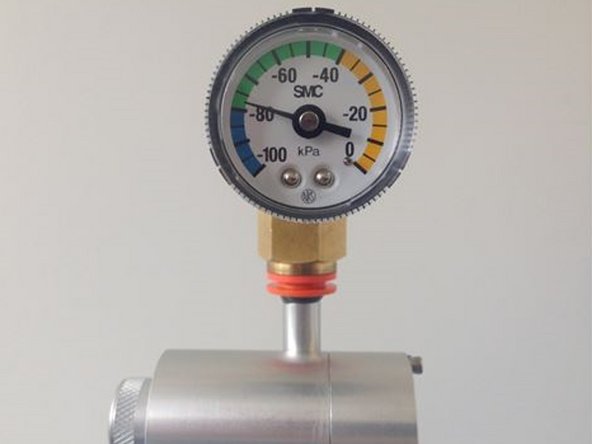
Fit the vacuum gauge to the inlet (above cyclone) and test for leaks (link).
-
-
-
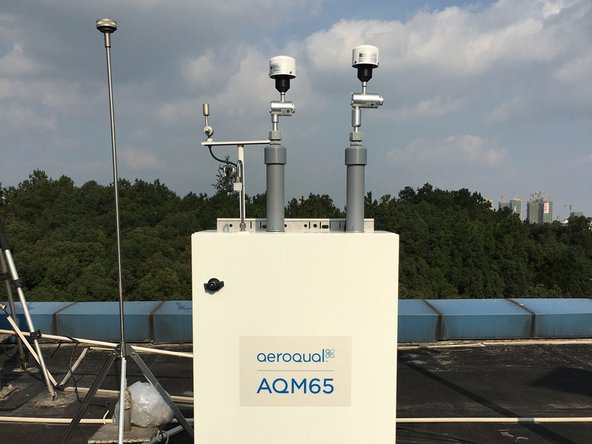
If your AQM 65 has two particle monitors, the PM10 inlet is fitted on the right side and the PM2.5 is fitted on the left side.
-
-
-
For extra help, watch our video.
-


For further support, contact Technical Support.
For further support, contact Technical Support.
Cancel: I did not complete this guide.
2 other people completed this guide.
