
Video Overview
-
-
It is recommended to remove power to the instrument while swapping out the module
-
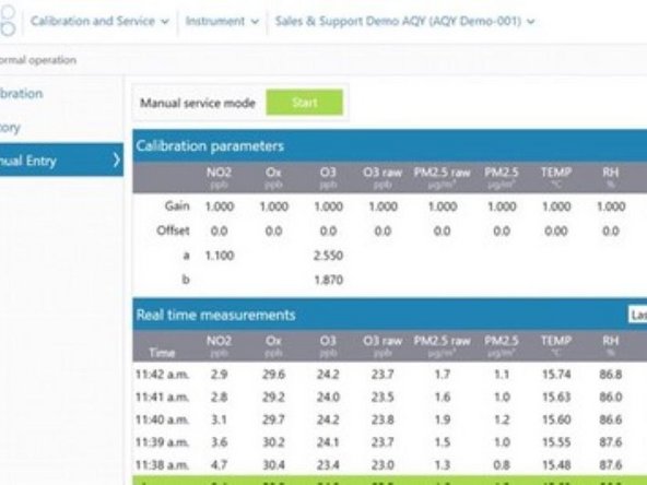
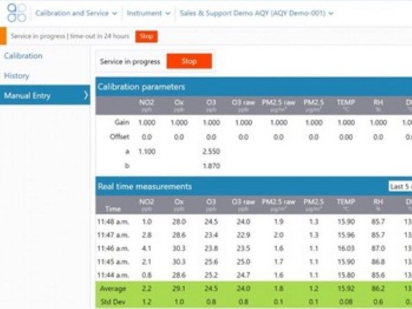
If power cannot be removed, enter service mode so any fluctuations in the data caused from this activity can be excluded from air quality reports
-
-
-
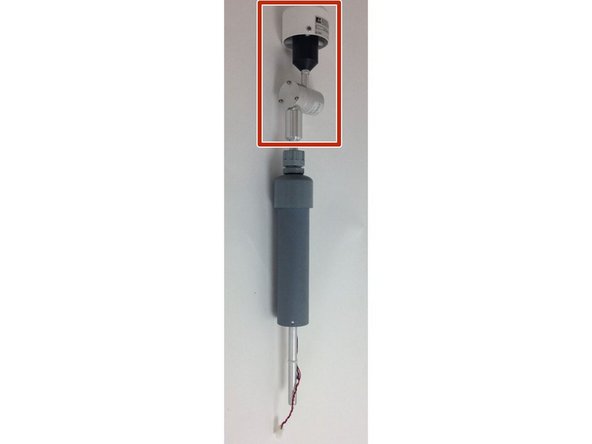
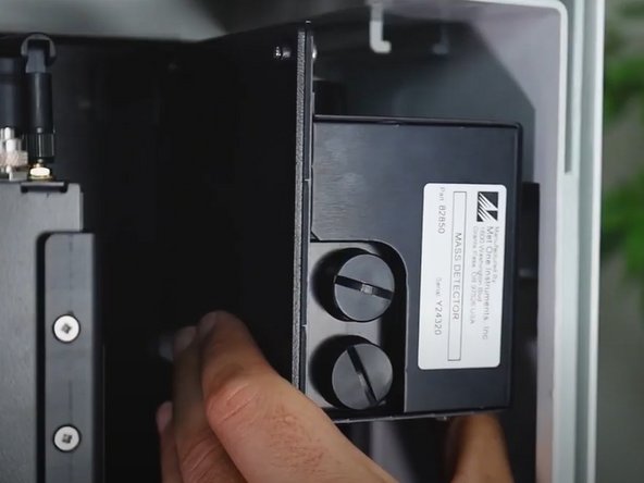
Open the instrument enclosure and locate the module to be replaced
-
The module will either be a MetOne model 82850 - Particle Monitor
-
OR model 9722-1 Particle Profiler
-
-
-
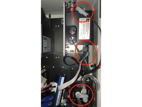
Prepare the module to be removed by disconnecting the tubing and cables:
-
Unplug the inlet heater power cable (red/black)
-
Unplug the module power cable (blue/black)
-
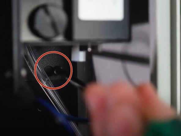
Unplug the data cable (a ribbon cable with a DB9 plug)
-
Unplug the Purge and Sample tubing gas connections from the pump module
-
-
-
Remove the TSP head and sharp-cut cyclone adaptor (if sharp-cut is present)
-
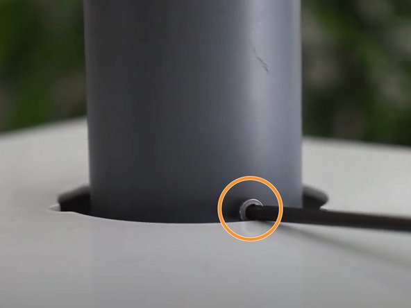
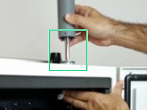
Remove the three retaining screws at the bottom of the PVC inlet tube using either an Allen key or small Philips head screwdriver (depending on the age of your instrument)
-
Gently lift to remove the outer grey PVC inlet tube and inlet heater
-
-
-
The module can now be removed:
-
Loosen the 3 backplate screws so the module mount can be slide out. DO NOT remove these screws
-
Remove the module, still attached to the aluminum module mount
-
-
-
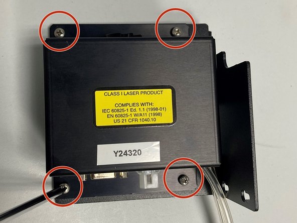
Using a large Philips screwdriver, remove the four screws holding the module to the mounting bracket
-
Mount new module to the mounting bracket with identical orientation using the same four mounting screws and tighten
-
Note the tubing connections should face the backplate
-
Install the new module onto the backplate and tighten the 3 backplate screws
-
Put aside the old module. Use the packaging from the Hot-swap module to return your old module
-
-
-
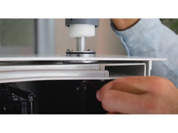
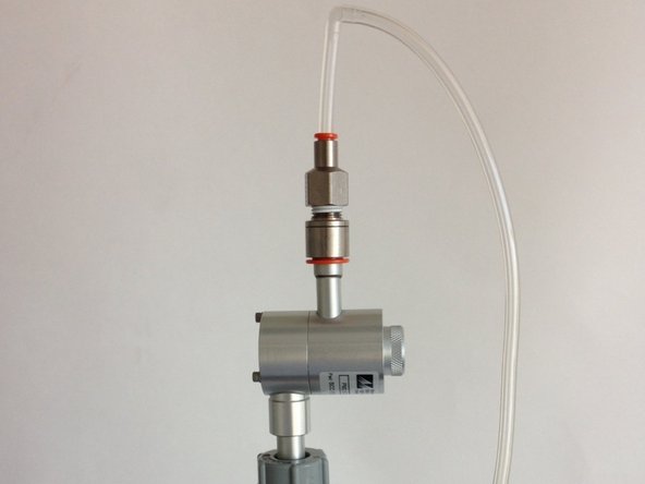
Carefully thread the aluminum inlet tube, as well as power cable and plug for the heater, through the mounting ring
-
Push the tube all the way into the optical module
-
Ensure that you insert the inlet tube past the o-rings; you will feel the tube stop at the base of the module
-
If it doesn’t go all the way in, add more length by:
-
Loosening the grey retaining nut on the top of the inlet
-
Sliding the rubber grommet up the tube and re-tighten the retaining nut
-
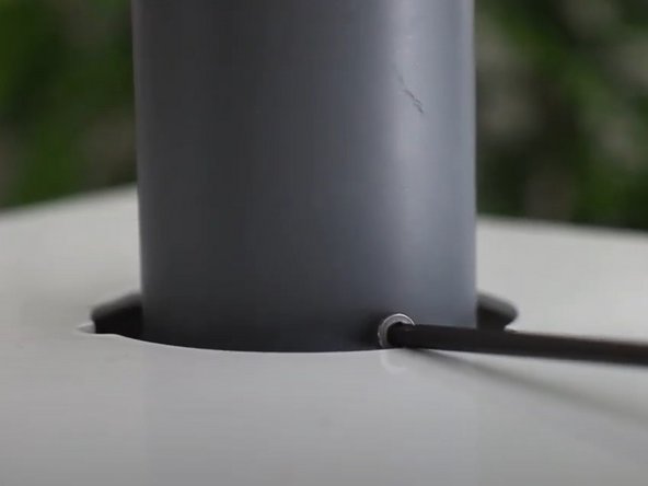
Add and tighten the three retaining screws on the PVC inlet tube
-
DO NOT re-install the sharp-cut cyclone and TSP head until a flow check is completed as per Step 9
-
-
-
Plug everything back in as it was when starting the work:
-
Connect the inlet’s heater plug (red/black) to the plug coming from the optical engine (red/black)
-
Connect the data cable (a ribbon cable with a DB9 plug)
-
Reconnect the tubing. The tube labelled sample to sample connector. The tube labelled purge to purge connector
-
Connect the module power cable (blue/black) to the bottom side of the module
-
Make sure all the cables and tubing are cleanly placed and will not be "pinched" when the door is closed!
-
-
-
Turn power to the monitor back on again if it has been turned off in step 1
-
If not already done, ensure Service mode has been enabled
-
-
-
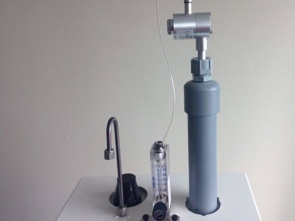
After re-installation of the module, it must be tested for proper operation.
-
A constant flow is essential to ensure the sharp cut cyclone is separating out the correct particle size for measurement depending on the module type
-
The flow rate of the 82850 particle monitor must be 2.0 LPM ± 0.05 (between 1.95 and 2.05 LPM).
-
The flow rate of the 9722-1 particle profiler is 1.0 ± 0.05 LPM (between 0.95 and 1.05 LPM).
-
-
-
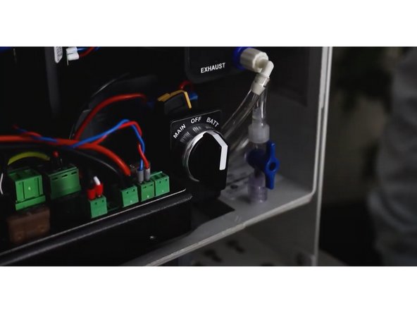
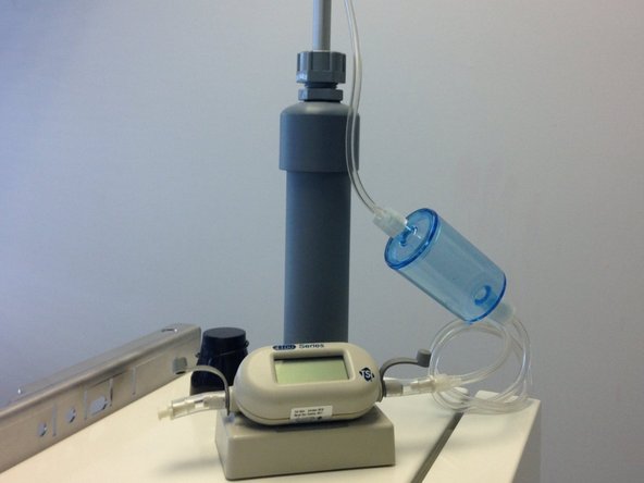
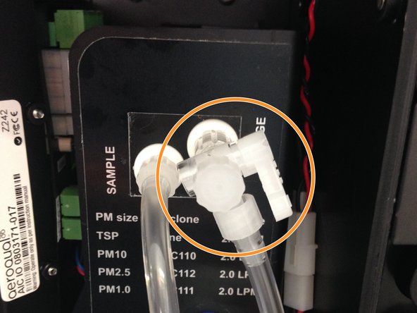
Adjust the sample flow by pulling the adjustment knob outwards, turning the knob to increase/decrease flow, and pushing the knob back in to lock when desired flow has been reached.
-
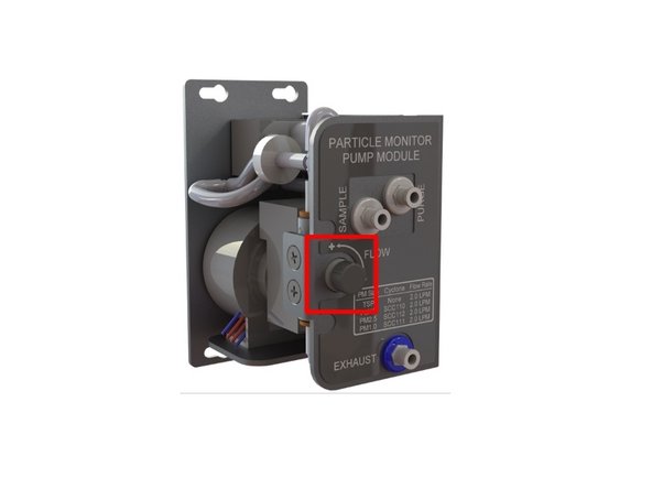
If the flow isn't correct, adjust the sample flow valve which is located on the face plate of the pump module, until the flow reads 2.0 LPM ± 0.05 (between 1.95 and 2.05 LPM).
-
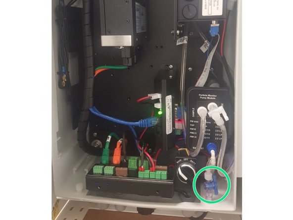
To adjust the flow on older monitors, fully close the purge valve by pushing the valve handle towards the pump module. Adjust the sample flow valve, located at the bottom of the enclosure under the PDI cover, until the flow reads 2.2 LPM. Then slowly re-open the purge valve until the flow reads 2.0 LPM ± 0.05 (between 1.95 and 2.05 LPM).
-
If you can't reach the required flow rate, there may be a leak, the sample and purge filters may be dirty, or the pump may need replacing.
-
-
-
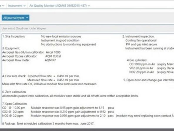
Record the results of this service activity in the monitor's journal
-
Exit service mode if power was not removed
-
-
-
Follow the procedures provided by an Aeroqual representative to send your module to MetOne.
-


For further support, contact Technical Support.
For further support, contact Technical Support.