
Introduction
Zero calibration can be performed on all gas modules simultaneously because all gas modules are sampling the same zero air source. The exception is CO2 which is zero calibrated separately.
It takes approximately 30 to 40 minutes for all of the modules to stabilize towards zero air, after which all offsets can be changed quickly, one after the other, and in any order, using either the Manual Entry or the Calibration areas of the Calibration and Service app.
If you have an AQS 1, use this procedure to zero calibrate your O3, NO2, CO and VOC gas modules. If you have an AQM 65, use it to zero calibrate your O3, NO2, NOx, SO2, CO, H2S and VOC gas modules.
If your monitor uses the Ox/O3 system to measure NO2, you can also use this guide to zero calibrate your Ox module.
Gas modules must be zero calibrated using zero air. N2 can’t be used.
We recommend you leave any failed modules running in the monitor throughout the zero and span calibration process. After you’ve calibrated the remaining modules, you can open the door to the monitor and remove the failed modules for inspection.
To understand how often you should perform this service activity, click here.
Tools
-
-
If you haven't already done so, turn on the AirCal 1000 and switch on the pump override switch on the back panel for at least 30 mins before starting the calibration. (The AirCal 1000 takes time to warm up and become stable).
-
The pump inside the calibrator draws ambient air in through the zero air inlet on the back. The ambient air passes through scrubbers to produce ‘zero air’.
-
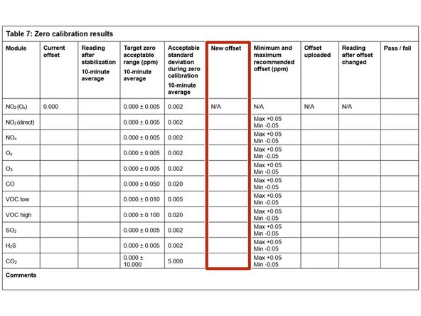
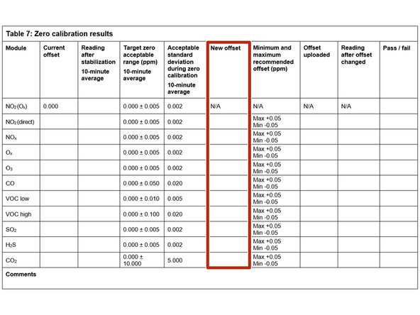
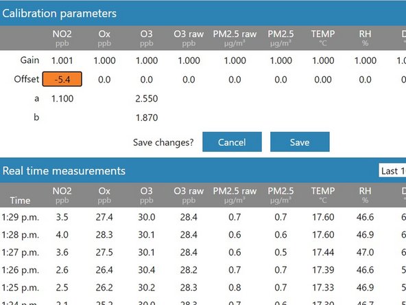
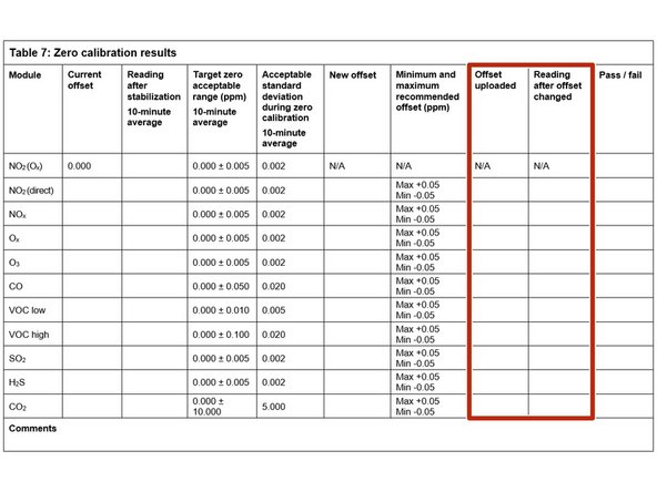
As the monitor is warming up, record the current offsets for each of your gas modules in the Current offset column in table 7 of the calibration form.
-
If an Ox module is fitted, NO2 doesn't have a zero offset adjustment.
-
-
-
Remove the Kynar fitting (inlet mesh filter) from the monitor’s gas inlet.
-
Connect the 3-way tee to the inlet.
-
Use the flow assembly that came with your AirCal 1000 (¼ OD PTFE tubing and compression fitting) to connect the outlet on the front of the AirCal 1000 to one side the tee.
-
Leave the other side uncapped.
-
With the calibrator connected, you should notice excess zero air flowing out the open side of the tee.
-
Double-check the connections are safe and secure.
-
The AirCal 1000 isn’t IP rated, so you need to take care when operating outdoors.
-
-
-
Wait 30 to 40 minutes for the module readings to stabilize towards zero air.
-
To determine if stabilization is successful:
-
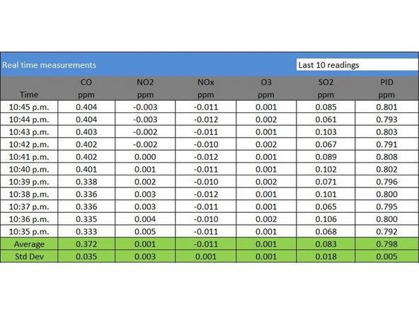
Look at the standard deviation over a ten-minute period in the Manual Entry (shown) or Calibration areas of the Calibration and Service app.
-
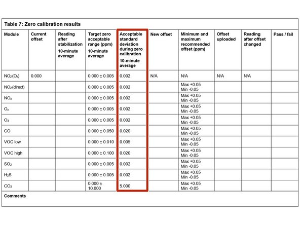
See if they fall within the acceptable range listed in the Acceptable standard deviation during zero calibration column of your calibration form.
-
To be stable, the readings mustn't be increasing or decreasing and within acceptable range.
-
If the values don’t stabilize, write fail in the Pass / fail column and move on to next module.
-
-
-
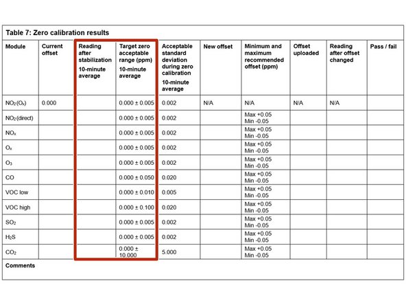
Record the stabilized reading from the 10-minute average in the Reading after stabilization column.
-
If the stabilized value is within the accepted range (see Target zero acceptable range column), no offset adjustment is required. Write pass in the Pass / fail column and move on to next module.
-
If the stabilized value is outside the accepted range, you need to make an offset adjustment.
-
-
-
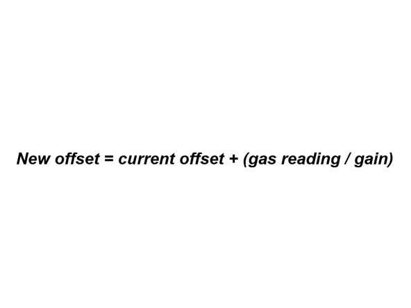
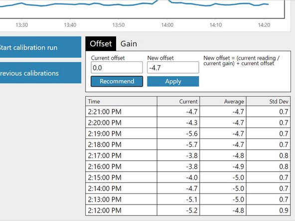
If you're using the Manual Entry area to upload offset adjustments, you need to calculate your new offset using the equation shown.
-
To make the calculation, you need to know the module's:
-
Current offset
-
Current gain
-
10-minute average reading.
-
Record the calculated offset in the New offset column.
-
-
-
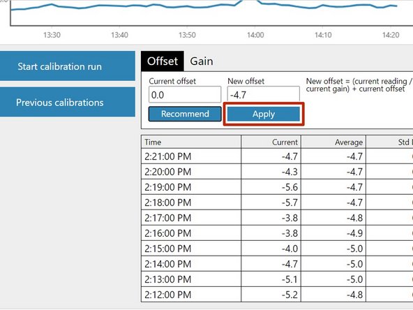
If you're using the Calibration area to upload offset adjustments, select the correct gas channel and click the Recommend button to calculate the offset for your selected gas.
-
Record the calculated offset in the New offset column.
-
To learn more about the functionality in the Calibration area, go here.
-
-
-
Gas modules can be offset adjusted in any order.
-
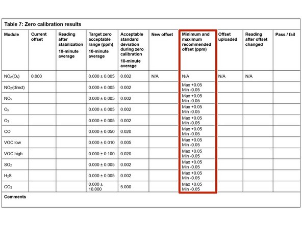
If the new offset is within the accepted range (see the Minimum and maximum recommended offset column), you can upload your new offset.
-
If you're using the Manual Entry area, click the appropriate cell, type in the new value and click Save.
-
If you're using the Calibration area, simply click the Apply button.
-
It might take several minutes for the offset to be applied and to see the changed readings.
-
If the new offset is outside the accepted range, don’t upload the offset. Write fail in the Pass / fail column and move on to next module.
-
-
-
Record the offset you uploaded in the Offset uploaded column.
-
Wait 2 or 3 minutes then record the current reading in the Reading after offset changed column.
-
Confirm the reading is within acceptable limits. If yes, write pass in the Pass / fail column. If not, write fail.
-
Move on to next module.
-
-
-
There may be times when either the module doesn’t stabilize, or a very large positive or negative offset is calculated. Make a note of this in the journal and then carry on with the rest of the zero calibration. Don’t open the door to check the module because this causes temperature instability.
-
The journal automatically records any changes you apply to the offset so you don't need to make any manual entries.
-
-
-
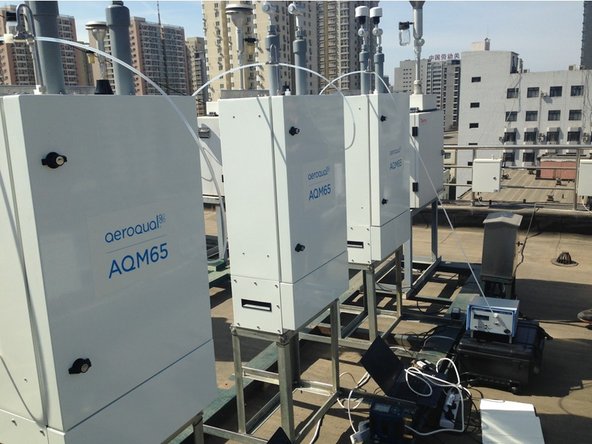
The outlet flow rate of the AirCal 1000 is fixed at approximately 2.5 LPM which means you can use it to calibrate more than one monitor simultaneously.
-
In this scenario, connect the flow assembly for the second monitor to the open end of the inlet tee. Repeat this, making sure the last monitor in the chain has an open tee.
-
You need to know the total inlet flow rate for your chain. You should still see excess zero air flowing out the open side of the last tee.
-


For further support, contact Technical Support.
For further support, contact Technical Support.
Cancel: I did not complete this guide.
4 other people completed this guide.
Attached Documents
