
Introduction
The Series 900 / Series 930 alarm and 4-20mA output scale settings are configured using Aeroqual’s fixed monitor configuration software.
To configure your monitor by computer, you need an RS232/RS485 or USB/RS485 converter. There are many RS232/RS485 converters available on the market, however only certain brands function well with Aeroqual products.
Aeroqual can supply a USB/RS485 converter suitable for configuring your S900 or S930. Contact your account manager or sales@aeroqual.com for more information.
This user guide assumes you have already installed the monitor’s configuration software and downloaded the FTDI software cable driver.
Tools
No tools specified.
Parts
-
-
Plug the USB to RS485 converter cable into the USB port of your computer.
-
Wire the RS485 outputs into the monitor using the table and diagram to guide you.
-
-
-
Power up the monitor.
-
Run the fixed monitor configuration software on your computer.
-
Enter the Port ID of your monitor.
-
All new products have a default ID of 1.
-
Click Download to download your monitor's current settings.
-
Check the settings.
-
-
-
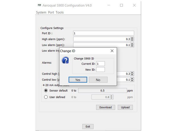
Click Port from the menu bar and select Change port ID from the drop-down.
-
Enter a new ID in the range 1 to 255 and click Yes.
-
If you're setting up a network, make sure each monitor has a unique ID, otherwise there'll be conflicts and data loss.
-
-
-
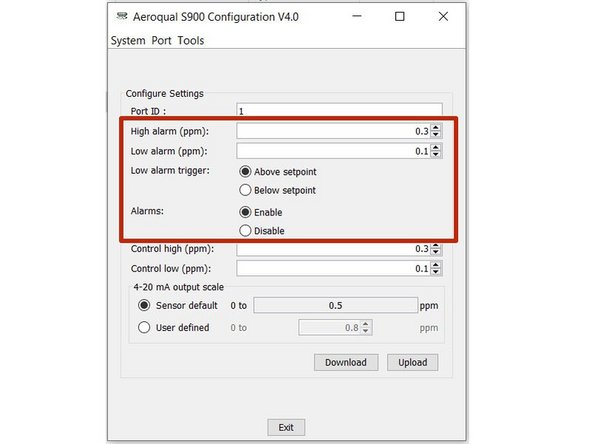
Make sure Enable is selected beside the Alarms option.
-
Adjust the alarm set points by typing in new values or using the up and down arrows in the High alarm (ppm) and Low alarm (ppm) fields.
-
The high alarm set point must be greater than low alarm set point.
-
Select Above setpoint or Below setpoint to determine whether the low alarm activates when the concentration goes above or below the set point.
-
-
-
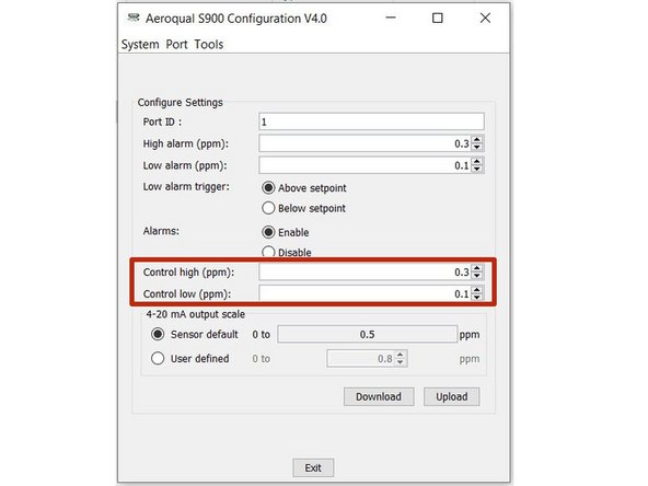
To determine when an external device such as an ozone generator operates, enter values in the Control high (ppm) and Control low (ppm) fields.
-
The external device will be on when the concentration is rising in the range from below control low until it hits control high when it turns off. It remains off until the concentration falls below control low.
-
The control high value must be greater than the control low value.
-
-
-
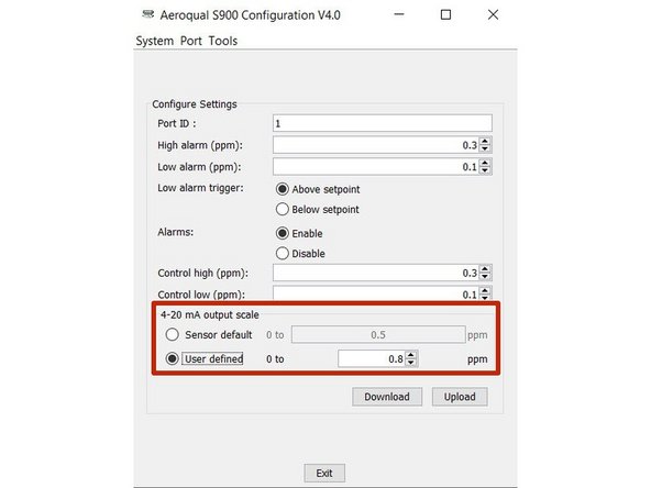
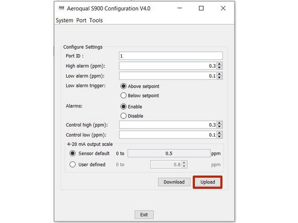
The 4-20mA output scale sets the gas concentration scale.
-
Each sensor head type has a default setting.
-
To change the scale, select User defined in the 4-20mA output scale area of the screen.
-
Enter the value that corresponds to 20mA.
-
-
-
Click Upload to upload your new settings to the monitor.
-


For further support, contact Technical Support.
For further support, contact Technical Support.
Cancel: I did not complete this guide.
7 other people completed this guide.
