
Introduction
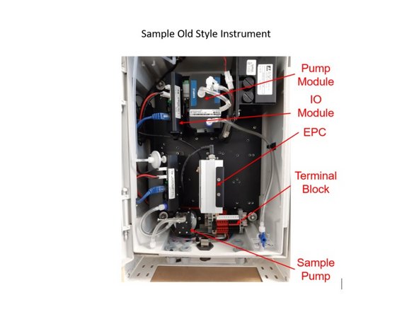
If you have an AQS 1 or Dust Sentry with an original DIN rail-based power system (including AUX module), you can upgrade to the new power and data interface (PDI), which offers more functionality and makes some operations easier.
The PDI Upgrade Kit converts the power system as well as the sub-chassis and cover.
Important notes
- The upgrade involves wiring of power supply connections, so it should be performed by a suitably qualified technician.
- The monitor must have an ARK-1123 or ARK-1124 embedded PC (ePC). If the monitor has the ARK-1123, you can only connect one third-party sensor after the upgrade.
- The monitor must be running Aeroqual Connect V1.17.2 or later.
- The monitor must have the latest back plate, which has additional holes. Monitors built after December 2017 (e.g. S/N: DS XX122017-YYY) will likely have the new back plate.
- To ensure the monitor maintains its certification, you should maintenance check it for leak, flow and zero after you’ve completed the upgrade.
-
-
The power and data interface upgrade involves wiring of power supply connections, it should be performed by a suitably qualified technician.
-
Before starting, disconnect power from the instrument.
-
Open the monitor door.
-
Remove the door by removing the hinge pins. Pull the top hinge pin down, and pull the bottom hinge pin up.
-
Take care when removing the door pins, it is possible to snap the pins during removal.
-
-
-
There are three internal protrusions near the bottom of the door that need to be trimmed to enable the door to close after the new power and data interface is installed.
-
Be aware that plastic dust may be generated in the next step.
-
Trim the three protrusions to less than 5 mm in height. This can be done using a mill or grinder for the best finish, or by drilling out the center of the protrusion with a large drill bit and removing any excess with side cutters.
-
The appearance of the protrusions can be cleaned up using a file.
-
-
-
Disconnect power to the monitor.
-
Remove all wires from the terminal block.
-
Depending on your monitor configuration, it may be easier to first remove the embedded PC (ePC) or other modules.
-
Remove the terminal block by removing the two screws holding the DIN rail in place.
-
-
-
This section applies to AQS monitors only.
-
Gas exhaust tubing connects the gas module tubing assembly to the pump tubing assembly.
-
Snip the exhaust tubing approximately 100 mm after module tubing assembly - see image.
-
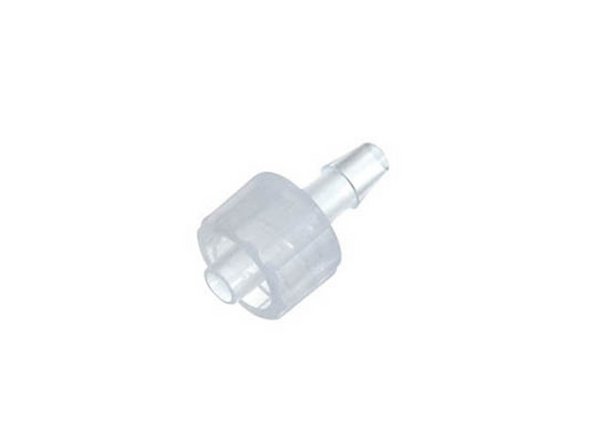
Insert the male luer fitting supplied with the PDI upgrade kit.
-
-
-
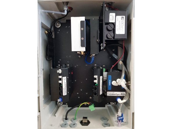
To prepare the monitor for the PDI, the the modules need to be re-arranged.
-
Remove the gas sampling pump by removing the 2 screws on the pump bracket, set it aside.
-
Rearrange the PM sampling modules and ePC to match the configuration shown.
-
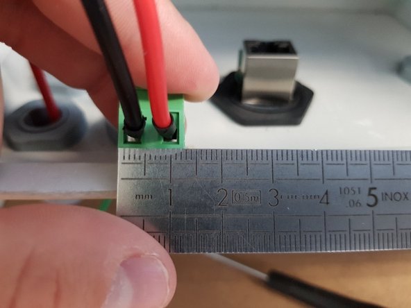
Fit a black ferrule to each of the power supply wires (including ground), and fix them in the large three-way green terminal block.
-
If powering the instrument by battery, insert the wires from the battery terminals through the glands in the bottom of the instrument, and fix them in the large green two-way terminal block.
-
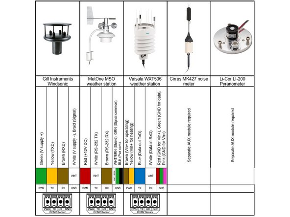
If using external sensors, insert the wires from the sensors through the glands in the bottom of the instrument. Fix them in the four-way green terminal blocks provided with the PDI upgrade kit.
-
-
-
Temporarily remove all gas modules in order to make room to route cables.
-
If there are any cable saddles on the underside of any modules on the bottom row of the instrument (as shown) remove them to make room for the PDI assembly.
-
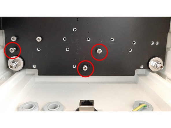
Loosely install 3 x M4x10 screws in the locations indicated. These are used to mount the power and data interface sub-chassis.
-
-
-
Attach all ePC cables to the ePC: Power, Module data cable (blue DB9-RJ45), COM cables (orange and green DB9-RJ45) USB, and WiFi antenna.
-
ePC Version: ARK 1123 or ARK 1124
-
Module data cable: COM1, top of EPC
-
COM Cables: COM, bottom of EPC (only one port available)
-
Attach all Modem cables to the modem (if used): modem power and antenna connection. Also ensure the ethernet cable is connected between the modem and the ePC.
-
Tidy the cables using three pieces of cable wrap as shown.
-
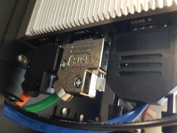
Ensure that the green COM cable labelled COM3 is plugged into the COM 3 port on the ePC, and the orange COM cable labelled COM2 is plugged into the COM 2 port on the ePC.
-
With some variants of the modem, it is possible to route the modem power cable through the cable wrap with the other cables. In the variant shown, the cable is not long enough, and thus is not included in the bundle.
-
-
-
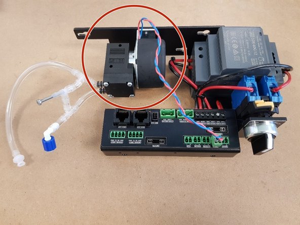
Retrieve the pump that was set aside earlier, and the PDI module assembly supplied with the upgrade kit.
-
Unscrew the pump from its mounting bracket.
-
Replace the tubing assembly on the pump with the new one as shown.
-
Attach white ferrules to the pump wires and screw them into the green plug as shown.
-
Ensure the wires are inserted with the correct polarity. If the pump is powered with the reverse polarity, it may be destroyed.
-
Mount the pump on the new PDI assembly bracket using its existing mounting screws. Plug the pump power plug into the connector labelled Pump on the PDI module.
-
-
-
Re-insert the gas modules.
-
Locate the PDI bracket onto the monitor back plate using the three screws fitted earlier.
-
Be aware that the screws on the underside of the bracket can get caught on the power cable. Tighten the three mounting screws after checking cable is free.
-
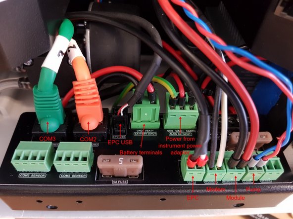
Plug all connectors into PDI module: MAIN DC INPUT and BATTERY INPUT, EPC USB, EPC COM2 and EPC COM3, MODEM power, and MODULE power.
-
If using external sensors, plug them in to the COM 2 SENSOR, and COM3 SENSORconnectors on the PDI module.
-
-
-
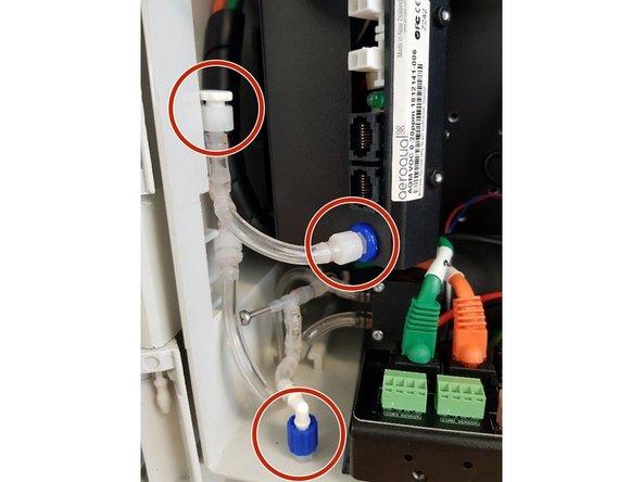
Re-connect the gas module exhaust assembly, ensuring that there are no kinks in the tubing. Ensure that all unused connectors are plugged. Ensure that the inlets to all gas modules are also connected.
-
Connect the blue Luer fitting on the exhaust of the pump tubing assembly to the instrument exhaust.
-
Plug in the module power cable between the PDI board and the particle IO module (or the closest module to the bottom of the instrument).
-
Connect the power and data cables between all modules as shown, use cable saddles to take up slack in the cables.
-
Plug the ePC to module data cable (blue DB9-RJ45) into the closest available module.
-
-
-
Any existing third-party sensors need to be connected using the PDI 's 4-way communication ports.
-
-
-
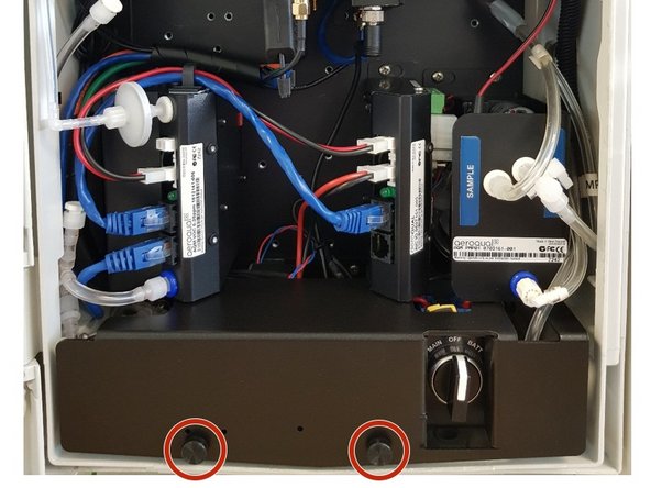
Install the cover plate and secure using the thumbscrews.
-
-
-
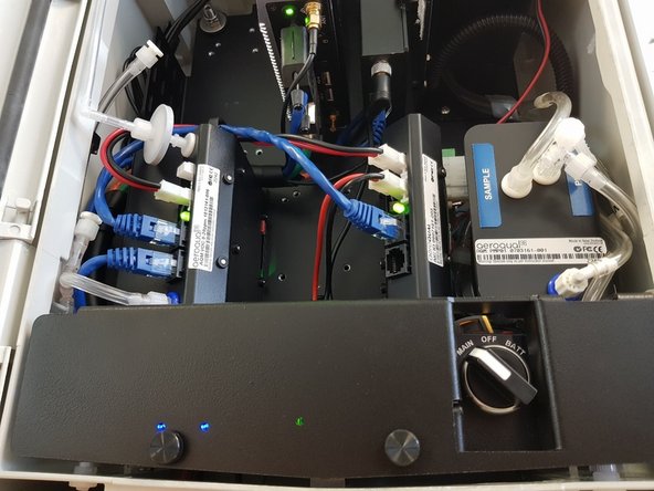
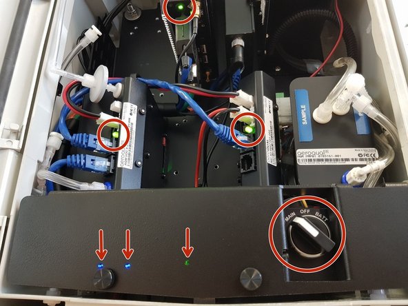
Reconnect power to the instrument and switch the instrument on using the power selector switch.
-
You should see a green light from the PDI module indicating that the module is switched on, and two blue lights indicating that the COM2 SENSOR and COM3 SENSOR ports are ready.
-
-
-
Go to Aeroqual Connect to complete the settings for external instruments.
-
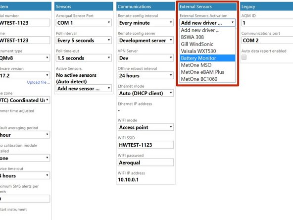
Go to the Configure app and to the column External Sensors.
-
Under External Sensors Activation, in Add new driver select Battery Monitor
-
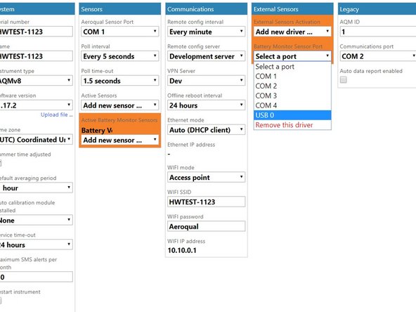
Battery Monitor Sensor Port appears, in Select a port select USB 0 then Save.
-
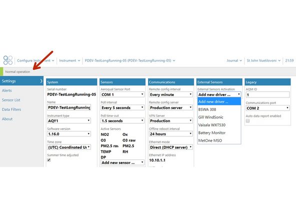
If the External Sensors Activation field does not appear in the External Sensors column, try to upgrade your version of Connect by selecting the latest version in the Software Version drop down box. Please make sure the Aeroqual Sensor Port is still COM1 after the upgrade.
-
-
-
Carry out the following checks to assess the function of the newly upgraded instrument:
-
When using mains power, the PDI lights should come on when the power selector switch is set to MAIN.
-
When using battery power, the PDI lights should come on when the power selector switch is set to BATT
-
When the device is powered on, all module lights should come on, and the ePC and modem lights should come on.
-
When the device is powered on, it should report Normal operation in Aeroqual Connect or Aeroqual Cloud. No modules should be listed as Offline or Failed.
-
If using the modem, the instrument should connect to Aeroqual Cloud when powered on.
-
In order for this product to maintain its certification, once the upgrade is completed, the instrument should be put through maintenance checks for leak, flow and zero.
-


For further support, contact Technical Support.
For further support, contact Technical Support.
Cancel: I did not complete this guide.
One other person completed this guide.

Team
