
Introduction
Wire the high alarm and low alarm pins to supply simple on/off switching to operate equipment which requires only an on, or off signal, such as an alarm.
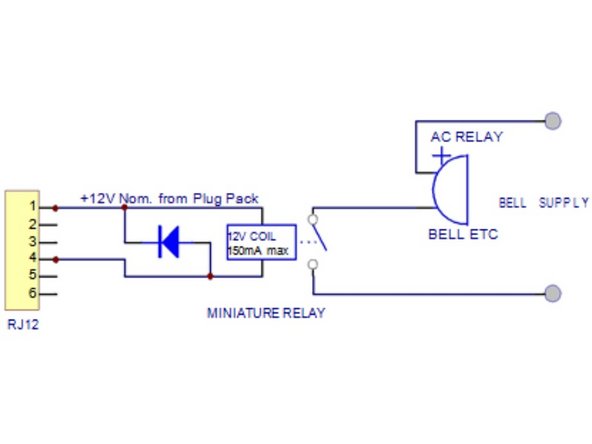
Note: All transistor outputs are open collector current sink. The maximum rating of these transistor outputs is 12VDC at 150mA. If you connect a relay or any other inductive load to the transistor outputs, a back EMF suppression diode must be fitted across the load.
-
-
The external connector requires an RJ12 connector. The pin designations for the external output connector are numbered 1 to 6.
-
1 = 12VDC (closest to the 12V DC power jack)
-
2 = Analogue output 0-5V
-
3 = Control
-
4 = High alarm
-
5 = Low alarm
-
6 = Ground (furthest from the 12V DC power jack)
-
The RJ12 connector offers two possibilities for wiring, either a switch to GND, or a switch to 12V output.
-
-
-
To switch to 12V output, wire to pins:
-
4 (High alarm) or 5 (Low alarm)
-
1 (12VDC).
-
If the 12V output is used, the power for the relay coil is supplied by the Aeroqual AC/DC adapter. In this case, make sure the relay coil doesn't draw more than 150 mA and that a protection diode is inserted across the relay coil.
-
The shown diagram is a typical wiring for a high gas level alarm.
-
Failure to insert a circuit protection diode may result in the circuit not working, and damage to the monitor if a voltage spike is created by the relay.
-
-
-
To switch to GND, wire to pins:
-
4 (High alarm) or 5 (Low alarm)
-
6 (Ground).
-
If the switch to GND output is used, make sure the relay coil doesn't draw more than 150 mA, that the voltage doesn't exceed 24V and that a protection diode is inserted with correct polarity across the relay coil.
-
Wiring for alarm will only operate while the handheld monitor is powered by the supplied AC/DC adapter.
-


For further support, contact Technical Support.
For further support, contact Technical Support.
Cancel: I did not complete this guide.
2 other people completed this guide.

Team
