Introduction
RGR CALKIT can be used to calibrate all Aeroqual sensor heads except ammonia, perchloroethylene, ozone and dust.
Gas calibration using the RGR CALKIT should always be completed in a location with adequate ventilation.
-
-
The calibration accessory has barbed fittings that are intended to fit with 1/8” ID tubing.
-
Care should be taken in selecting a tubing material that is appropriate for the type of gas that you will be using to calibrate the sensor head.
-
PVDF tubing is appropriate for most gases but the tubing's datasheet should be consulted for a full list.
-
Either side of the calibration accessory can be designated the inlet or the outlet.
-
Not all gas that enters through the inlet exits through the calibration accessory outlet; be advised that some gas exits through the sensor head exhaust. Depending on your calibration gas of choice and concentration levels, you may need to perform this calibration under a fume hood.
-
-
-
Make sure the valve on your flow gas regulator is fully off.
-
Screw the gas regulator onto your gas cylinder. When the regulator is correctly fitted, the pressure indicator will show the cylinder pressure.
-
Always point the cylinder and regulator away from yourself and others when attaching or removing a pressure regulator.
-
Secure the cylinder so it can't be knocked over while the regulator is attached.
-
-
-
Connect tubing to gas source and ventilation.
-
Either side of the calibration accessory can be designated the inlet or the outlet
-
-
Step 4 Attach the calibration accessory to the sensor head while the head is plugged into the Ranger
-
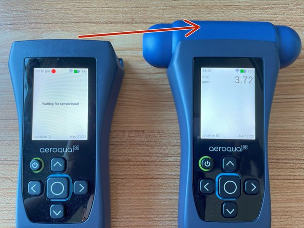
Attach the sensor head to Ranger
-
Turn Ranger On
-
Attach the calibration accessory to the sensor head
-
-
-
Check the cylinder pressure to ensure there's enough gas to perform the calibration (10% of full pressure should be enough).
-
Gently turn the regulator valve anticlockwise and flow the target gas at >1L/min until the reading stabilizes (about 10 minutes).
-
-
-
Wait for the gas reading to stabilize on the display of the Ranger
-
-
-
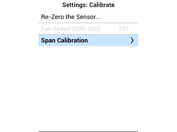
Press and hold the LEFT arrow key to enter the Settings menu
-
Navigate down and selectm 'Calibrate' and then ‘Span Calibration’
-
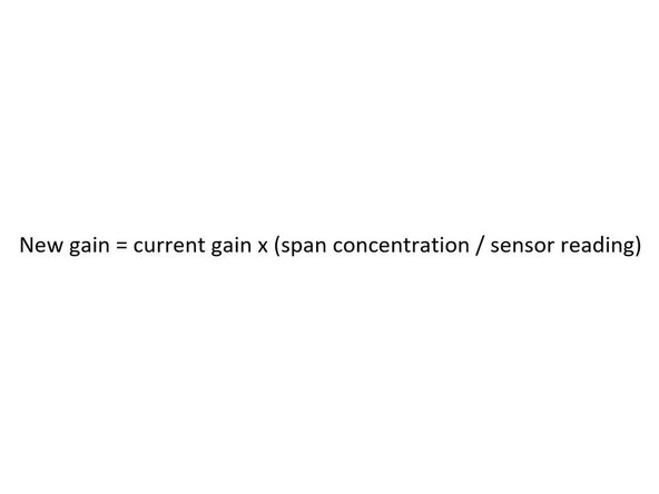
Enter the span adjustment menu and calculate the required gain using the formula
-
-
-
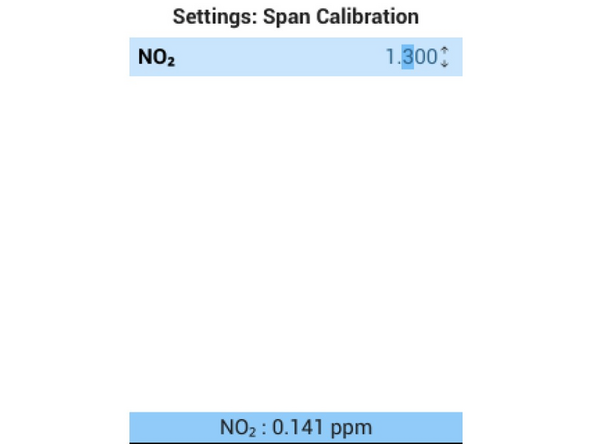
Adjust the gain value in the Span Calibration menu to match your calculated value
-
Press enter
-
Wait for the next sensor reading, which will have the new gain applied
-
The value is not applied until you press enter
-
The new gain value will be applied on the next measurement cycle; the value displayed at the bottom may take 1-2 minutes to update
-
Confirm the new reading matches your expected value.
-
Exit the span calibration menu.
-
-
-
Turn off the gas regulator.
-
Pack up.
-
-
-
If you remove the gas sensor head from any Ranger base, and attach it to a different Ranger base, the Span will be retained
-


For further support, visit Span calibration, How to test your sensor head , Sensors - VOC, or contact Technical Support.
For further support, visit Span calibration, How to test your sensor head , Sensors - VOC, or contact Technical Support.
Cancel: I did not complete this guide.
One other person completed this guide.